Needs-based cooling of control cabinets
A series of measurements taken in practical situations shows the benefits of the AirBLOWER control cabinet fan for needs-based cooling of control cabinets.
The fan system, which is designed for use with the duct-free AirSTREAM wiring system, homogenizes the climate in the control cabinet and breaks up the temperature layers that are created when hot air rises. The practical measurements also highlighted something amazing: the simultaneity factor* in one of the examined control cabinets was only 40 %. If this is taken into account when calculating effective power loss in the control cabinet, new possibilities arise with respect to needs-based air conditioning, reduction of total energy costs and CO2 savings.
Knowledge of the operating conditions is important when designing the air conditioning equipment in control cabinets. As these conditions are difficult to specify precisely, calculations usually factor in large safety reserves. A practical example shows the potential of needs-based air conditioning and how this can be tapped without compromising the operational safety of a system. During the course of the long-standing cooperation between LÜTZE and the Institute for Building Energy, Thermal Engineering and Energy Storage (IGTE) of the University of Stuttgart, practical measurements as well as detailed theoretical examinations were conducted. For instance, it was possible to make very precise predictions about the air current situation and the expected temperatures for various operating conditions.
Test series shows potential
During the test series, temperature measurements were taken in control cabinets used in industrial environments. These measurements are also required to validate theoretical examinations. The following is a detailed explanation of the results of the test series for one of the examined control cabinets, specifically, an assembly cabinet that controls a cyclic assembly process. This cabinet does not have any cooling equipment and works with a free cooling principle. According to the data provided by all manufacturers about the nominal power loss of the respective parts, a power loss of 500W dissipates into the control cabinet. If, in this case, a calculation is conducted with the heat analysis software AirTEMP that takes into account the spatial power loss distribution, temperatures of up to 73 °C can be expected in the air at the top of the control cabinet that works with free cooling (no air conditioning equipment). A simultaneity factor of 100% was used here. It was not possible to confirm the temperatures predicted under these conditions in the practical measurements. In fact, the temperatures in practice were far lower due to the much lower simultaneity factor. However, the temperatures measured in the control cabinet still exceeded the allowed level. Therefore, the control cabinet was equipped with an AirSTREAM.
Moving air
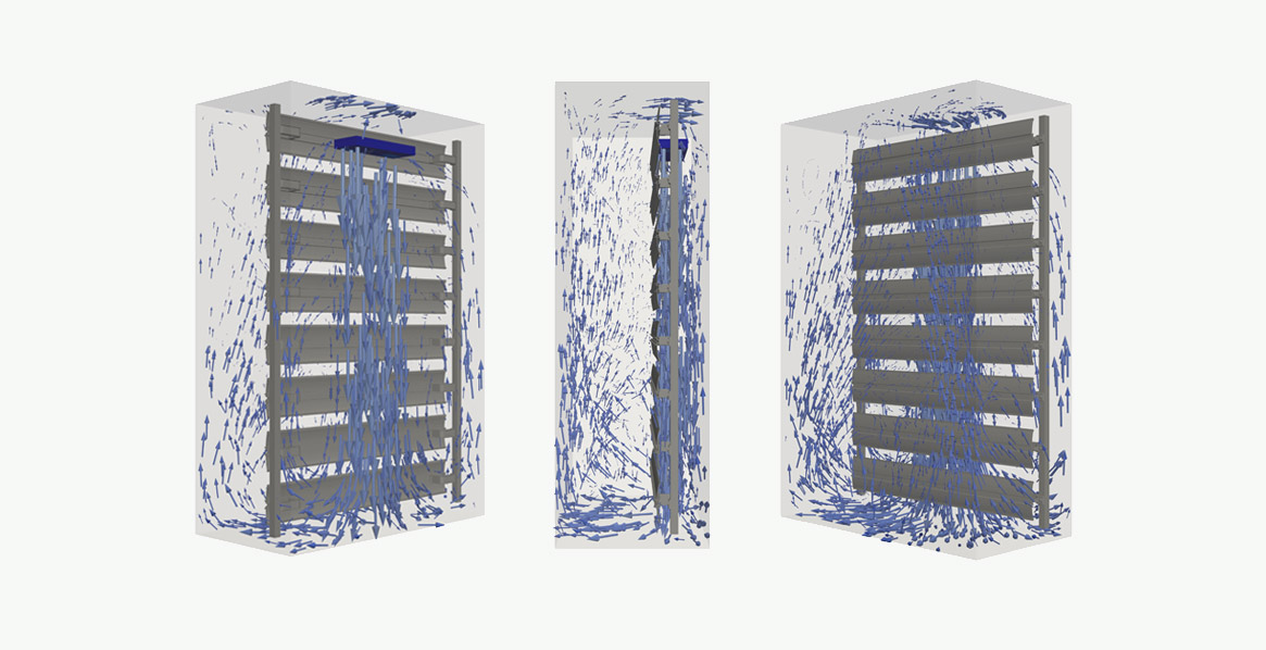
The AirBLOWER creates targeted circulating currents in the control cabinet. Here, a flow of air of up to 510m³/h is blown downwards behind the AirSTREAM frame and as a result, the air in the control cabinet flows around the AirSTREAM frame. Figure 1 shows the resulting current situation based on theoretical calculations. It clearly demonstrates how the air is circulating across the entire height of the control cabinet. As a result, areas with little or no airflow are minimized and air layers are broken up.
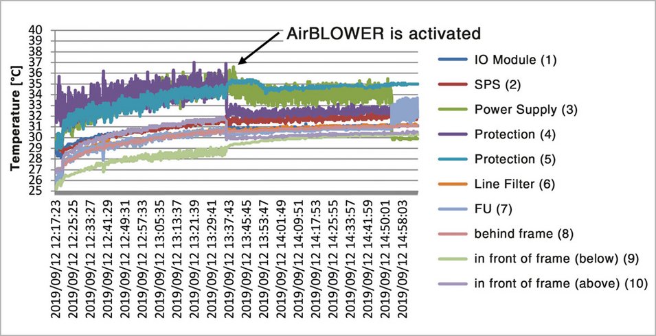
To verify the efficiency of the LÜTZE fan system mechanism, the temperatures were measured when an AirBLOWER was used. Figure 2 shows the temperatures that were measured. The AirBLOWER is operated with a 3-point control strategy. Based on the temperatures that the fan captures via its control unit and the 3 temperature sensors, the AirBLOWER is switched on when a configured temperature is reached. In the upper part of Figure 2, you can see how the temperatures initially increase at all measuring points. As the AirBLOWER is inactive at this time, a free cooling principle is used. Ultimately, the switching threshold of the AirBLOWER at one of the control positions is exceeded and it is activated, and immediately, the temperature increase stops at all measuring positions. The temperatures finally stay in a relatively steady and even range.
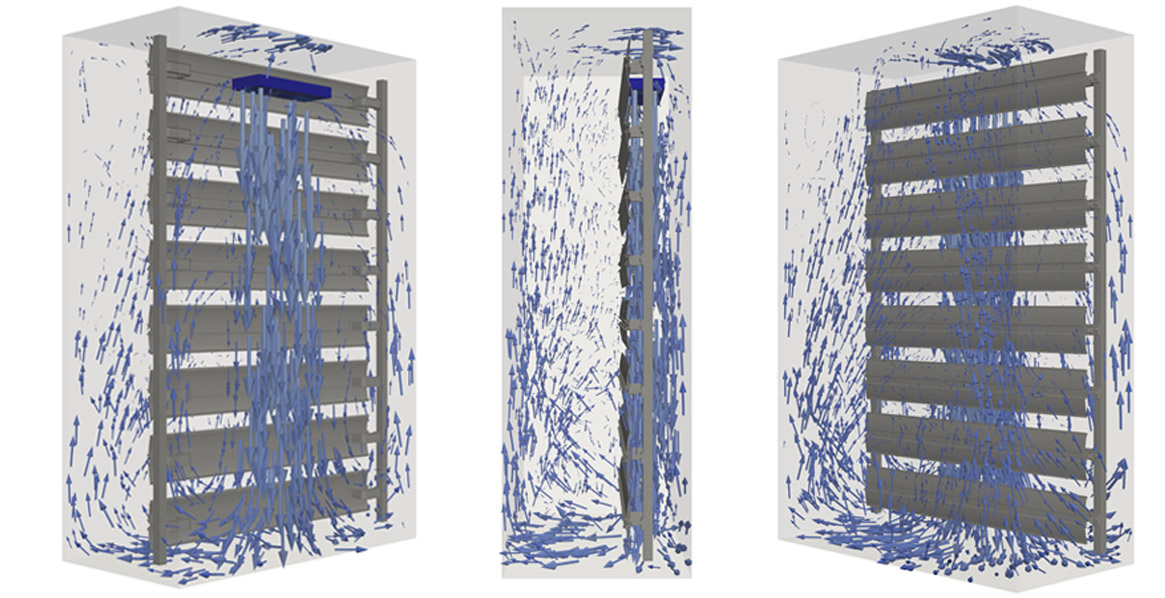
Figure 1: Circulation flow around the AirSTREAM frame with a fitted AirBLOWER fan system
Temperature layering is dissipated
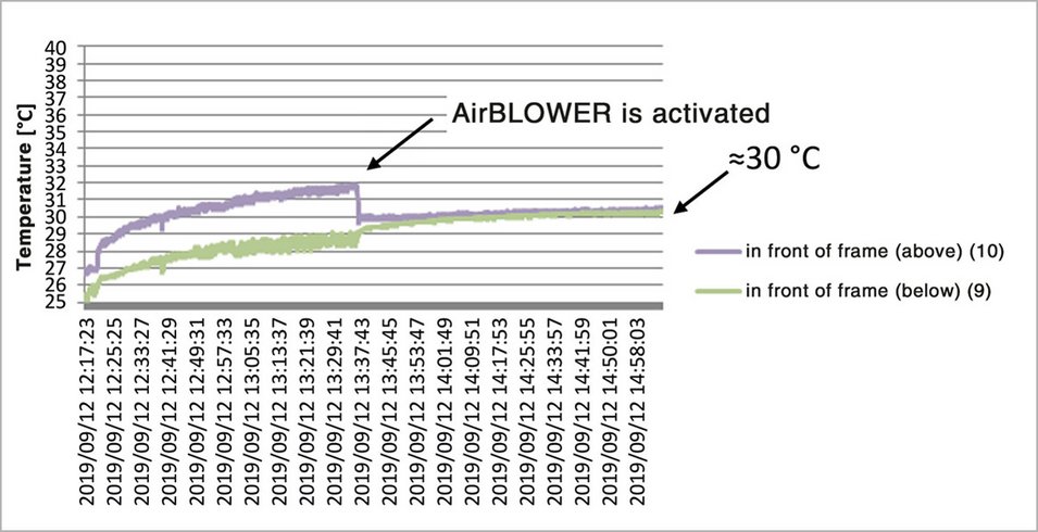
The remaining temperature fluctuations towards the end of the measuring cycle are due to the time-related clocking procedure of the system. The efficiency of the AirBLOWER fan mechanism was particularly impressive on examination of the temperatures in the upper and lower area of the free air volume in the control cabinet. The respective temperature curves are clearly shown in the lower section of Figure 2 and how that activation of the AirBLOWER completely dissipated the height-dependent temperature layering in the control cabinet. The targeted circulation current mixes with a high percentage of the control cabinet air and the parts are cooled more efficiently.
Determining the simultaneity factor
The mean temperature of the free air volume is 30°C if an AirBLOWER is used. In a theoretical examination with AirTEMP and an assumed simultaneity factor of 100 %, the temperature would be approximately 37 °C. Once again, this clearly shows the benefits of the AirBLOWER system. In a theoretical examination, the maximum temperature in the control cabinet during free cooling is approximately 36°K higher than if it is operated with an AirBLOWER. If the air is well mixed when operated with an AirBLOWER, the mean temperature in the free air volume is a good indicator of the power loss released in a control cabinet. This is because when there is no active cooling, the power loss needs to be completely discharged via the walls of the control cabinet.
This discrepancy between the theoretical examination and measurement, and the fact that the examined system is timed, leads to the conclusion that the simultaneity factor cannot equal 100 %. The actual simultaneity factor can be determined fairly precisely based on the practical measurements and the theoretical examinations. Here, the simultaneity factor is reduced during the theoretical examinations until a temperature of 30°C in free air volume is reached. Based on this procedure, a simultaneity factor of just 40% is achieved. This means that the effective power loss, which is essential when designing control cabinet air conditioning, is reduced from 500W to 200W. The following shows the impact of this on the predicted climate in the control cabinet.
Comparison of free cooling and operation with the AirBLOWER for simultaneity factors of 100 % and 40 %
Simultaneity factor of 100 %
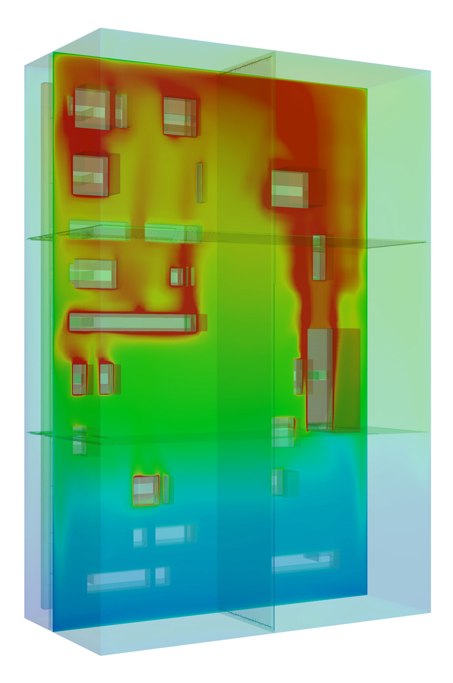
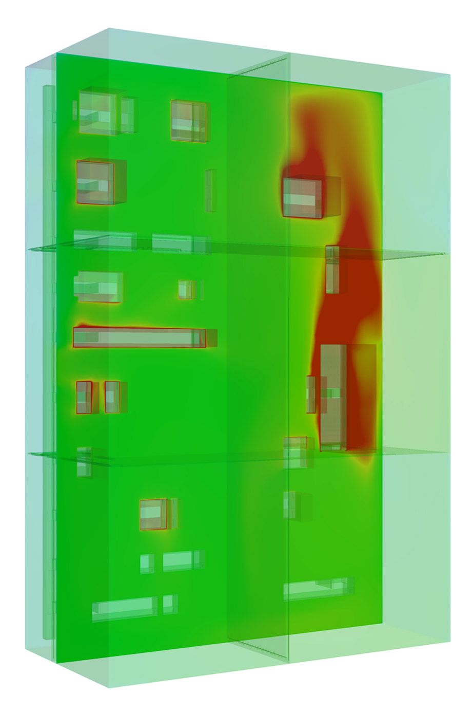
Free air volume
Theor. value: ≈37 °C

Simultaneity factor of 40%
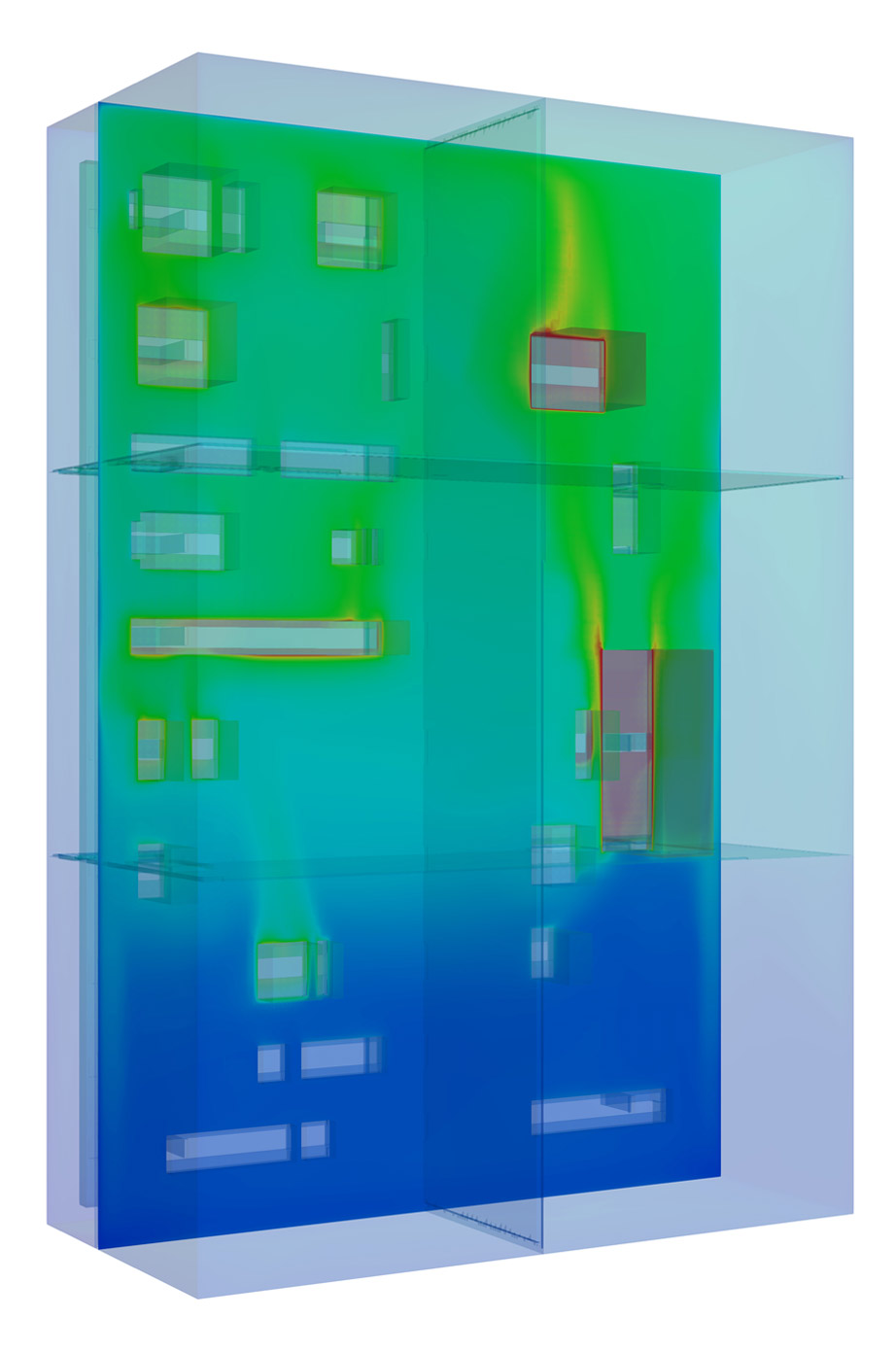
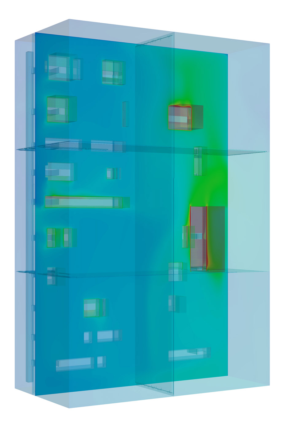
Free air volume
Measured value: ≈30 °C

Figure 3: Comparison of free cooling and operation with the AIRBLOWER for simultaneity factors of 100 % and 40 %
Controlling the climate in the cabinet
Figure 3 shows the conducted theoretical examination for the operating conditions 'free cooling' and 'operation with the AirBLOWER' at simultaneity factors of 100 % and 40 %. Here, the nominal power losses stipulated by the manufacturers were used. Regardless of the simultaneity factor that was applied, it is impressive that the AirBLOWER is able to dissipate the temperature layering and even hotspots. When looking at the free cooling case, the importance of the simultaneity factor and the assumed power loss distribution become evident. At a simultaneity factor of 100%, hotspots are created above almost every part. At a simultaneity factor of 40%, there is still evidence of temperature layering during free cooling but most of the hotspots have disappeared. If an AirBLOWER is also fitted, the climate in the control cabinet can be managed easily.
The homogenous moderate air temperatures (30 °C in the free air volume) increase the lifespan of the parts and reduce the probability of system failure. In permanent operating mode, the power consumption of an AirBLOWER is an average of 20W, which is negligible compared to an air conditioning unit.
Don't forget the ambient temperature
The impact of the ambient temperature also needs to be examined as a final key factor when designing the thermal equipment of the control cabinet. The temperature measurements recorded an ambient temperature of 25°C. This was used for the illustrated theoretical examination, although due to the installation situation, the ambient temperature may reach up to 40°C on hot summer days. This increase in the ambient temperature is transferred directly to the temperature inside the control cabinet. For instance, the temperature in the summer may be up to 15°K higher than the temperature when the measurements were taken, which is why it is essential that the AirBLOWER breaks up the temperature layers in the control cabinet.
The transition range in which a system can be operated without an air conditioning device can be increased, if the system is operated with an AirBLOWER. However, it is not possible to dispense with an air conditioning unit when the released power loss tolerance is exceeded and the expected permanent ambient temperature is high. Here too, the AirBLOWER helps by reducing the operating time of the air conditioning unit as far as possible. This also allows the best possible distribution of the energy-intensive cold that is produced. Homogenization of the inner temperature is a way towards needs-based cooling of control cabinets because only the cooling power that is actually required is supplied. In a next step, it is important to assess in detail the available potential to allow statements to be made about the reduction of operating costs and a reduction of the CO2 footprint. Other practical and theoretical examinations in this field are planned.
* The simultaneity factor takes into account the fact that all parts in a control cabinet are never operated at full power at the same time.
Authors:
Michael Bautz, Product Manager Cabinet, Friedrich Lütze GmbH
Wolfgang Heidemann, University of Stuttgart, Institute for Building Energy, Thermal Engineering and Energy Storage (IGTE)
Daniel Haag, University of Stuttgart, Institute for Building Energy, Thermal Engineering and Energy Storage (IGTE)
